Wiring a Perko Battery Switch
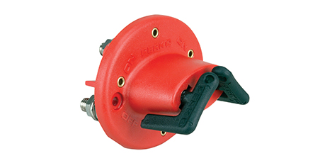
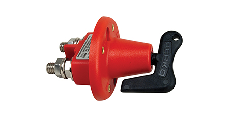
There are many ways to use a Perko Battery On-Off Switch. The most obvious (and most common) is simply to use it to turn off your battery when in storage so that your battery does not drain as quickly and is ready to go when you are. Like all Perko products, these time-proven switches are made in the USA. All switches are ignition protected.
But for boats with multiple engines and multiple batteries, using multiple on-off switches (sometimes in conjunction with a selector switch) can provide different benefits. Running with a selector switch in the both position (see selector switches) may not fully charge all batteries. But adding on-off switches to the circuit you can force the alternator to charge the battery you want charged.
If you have any questions or doubt about how to use, install or wire any battery switch, consult a certified marine electrician. Battery disconnect switches help manage the overall use of electrical power on-board. They are used to connect or disconnect electrical devices from the electrical system. They help to prevent battery drain during periods of inactivity. They allow for a quick and easy way to shut down the entire electrical system in an emergency. An optional key lock helps to prevent unauthorized use of the vessel.
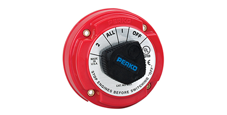
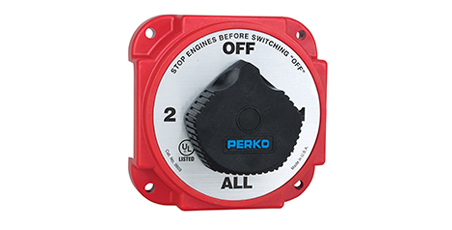
Perko battery switches are designed for surface mounting. Standard duty disconnect switches have bright red polycarbonate reinforced housings for safety with large easy-to-turn black knobs. The housing of the heavy duty switches are red fiber-reinforced polycarbonate.
Models with an “Alternator Field Disconnect” feature offer protection for Non-Unitized Alternators should the switch accidentally be turned to the “OFF” position with the engine running.
High conductivity studs are long enough to handle more than 1 cable and strong enough for torque needed for secure connections. Optional spacer ring (PN 0462DP0RED) allows for the use of larger cables.
Battery Switch Wiring Diagrams

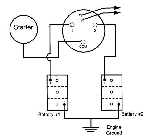
Switch Position indicates which battery (#1, All, #2) is connected to the engine.
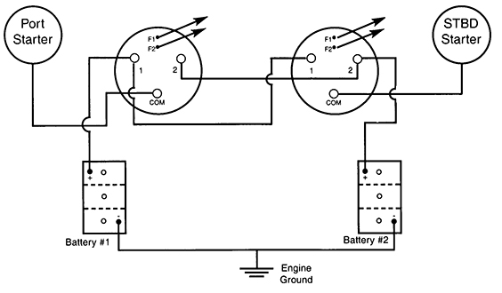
This allows either engine to be started by either battery. Port switch indicates which battery (#1, All, #2) is connected to the port engine and the starboard switch indicates which battery (#1, All, #2) is connected to the starboard engine.
The allows both engines to be used to charge Lighting Batteries. Port switch indicates which battery (port only, port lighting only) is connected to the port engine and the starboard switch indicates which battery (starboard only, starboard lighting only) is connected to starboard engine.


